

Where we deliver
The best‑placed asset the city already owns
A signal‑controlled junction is the one street location that already has mains power, a pole on every approach, a cabinet, and a communications route back to the control room. Everything a smart city wants to measure happens there — and almost every upgrade a city wants to make has to reach there anyway.
Why the junction
Power, poles, cabinet, communications — all in place
- Power at the pole, on every arm of the junction
- A cabinet with a controller already talking to Urban Traffic Control (UTC)
- Mounting height and sightlines that detection and cameras need
- A location the authority already owns, maintains and can access
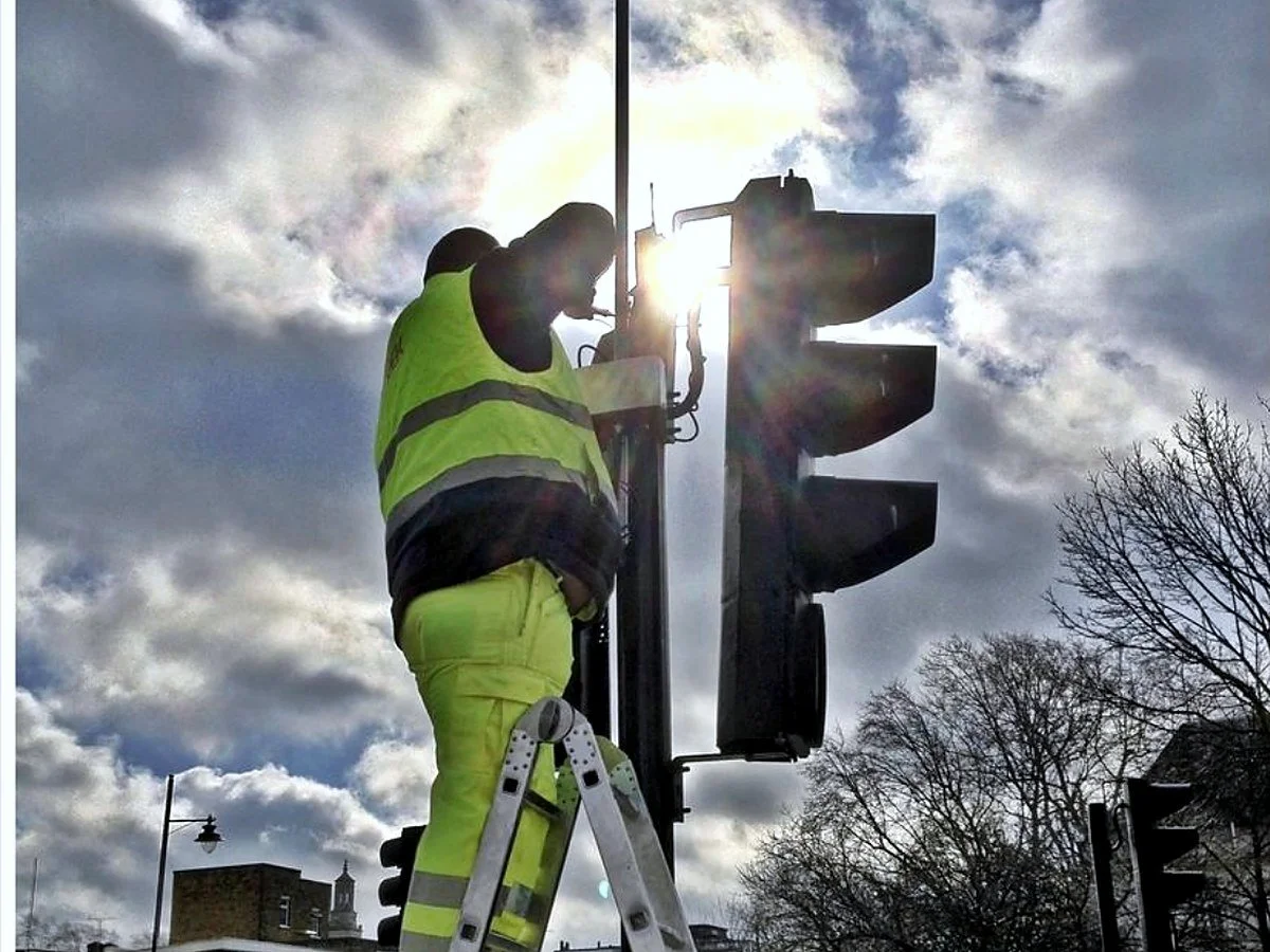
NOW Wireless kit mounted on a signal pole during a Transport for London installation.
Proven at scale
Built in the United Kingdom, running in UK cities for over two decades
NOW Wireless has designed and built its own wireless systems, detectors and traffic systems in the United Kingdom since 2002.
Figures describe deployed networks. Savings and performance depend on the existing cost baseline, site conditions and network design.
Part one
Connect the junction
Before a junction can be intelligent it has to be reachable. The first layer replaces a rented circuit to every cabinet with one self‑healing wireless network.
Wireless traffic lights
Every junction connected, without a circuit to every cabinet
Many authorities still rent a separate communications circuit for each traffic‑signal cabinet — an ongoing cost for a modest amount of operational data. A self‑healing wireless mesh replaces those circuits and, in suitable deployments, can reduce recurring communications costs by up to 90% while leaving capacity for cameras, sensors and edge AI.
- Compatible controllers reach UTC and Urban Traffic Management and Control (UTMC) over the mesh instead of a leased line or modem
- Powered from the signal pole; suitable retrofits avoid new inter‑junction circuits and trenching
- Every node carries powered Ethernet ports, so cameras, sensors, detectors and signs plug in with no extra circuit
- Links change frequency automatically on interference and reroute automatically on failure

A wireless traffic light: the signal, the camera and the node share one pole and one connection.
Fibre clusters
Where the fibre is, the cluster follows
Many councils are moving to fibre, so that is where a junction cluster starts. Fibre reaches the cabinet and every street object at the junction is served from it — every approach, every camera, every sensor on one connection.
- A fibre point at the junction connects the cluster of street objects around it
- All approaches served from the one fibre connection
- The catch: fibre is fixed in place. Adding a device somewhere new later means running fresh fibre to that spot — slow and expensive
- Which is exactly the problem the wireless cluster solves
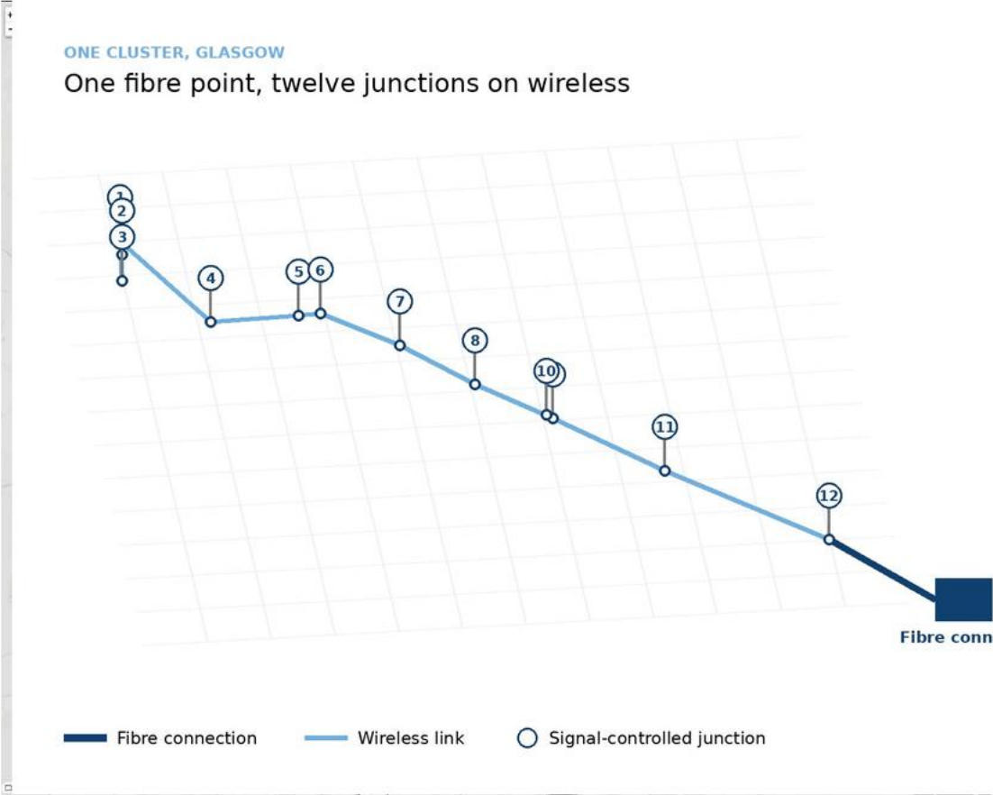
One Glasgow cluster: twelve junctions on wireless from a single fibre point.
Wireless clusters
Illuminate the street, then add devices anywhere
Our wireless illuminates the whole street at 5 GHz over line of sight. Drop a receiver anywhere in that line of sight and add a device — no trenching, no new fibre. If you already have fibre and want to extend it or hang another device off it, this is how.
- Add any device later on the same network: variable message signs, further traffic lights, remote detectors, CCTV
- We add our own software to every link so it works as a managed connection, not raw radio
- A central mesh manager controls the whole network — every wireless link and every device on it
- Extend a fibre cluster without touching the road
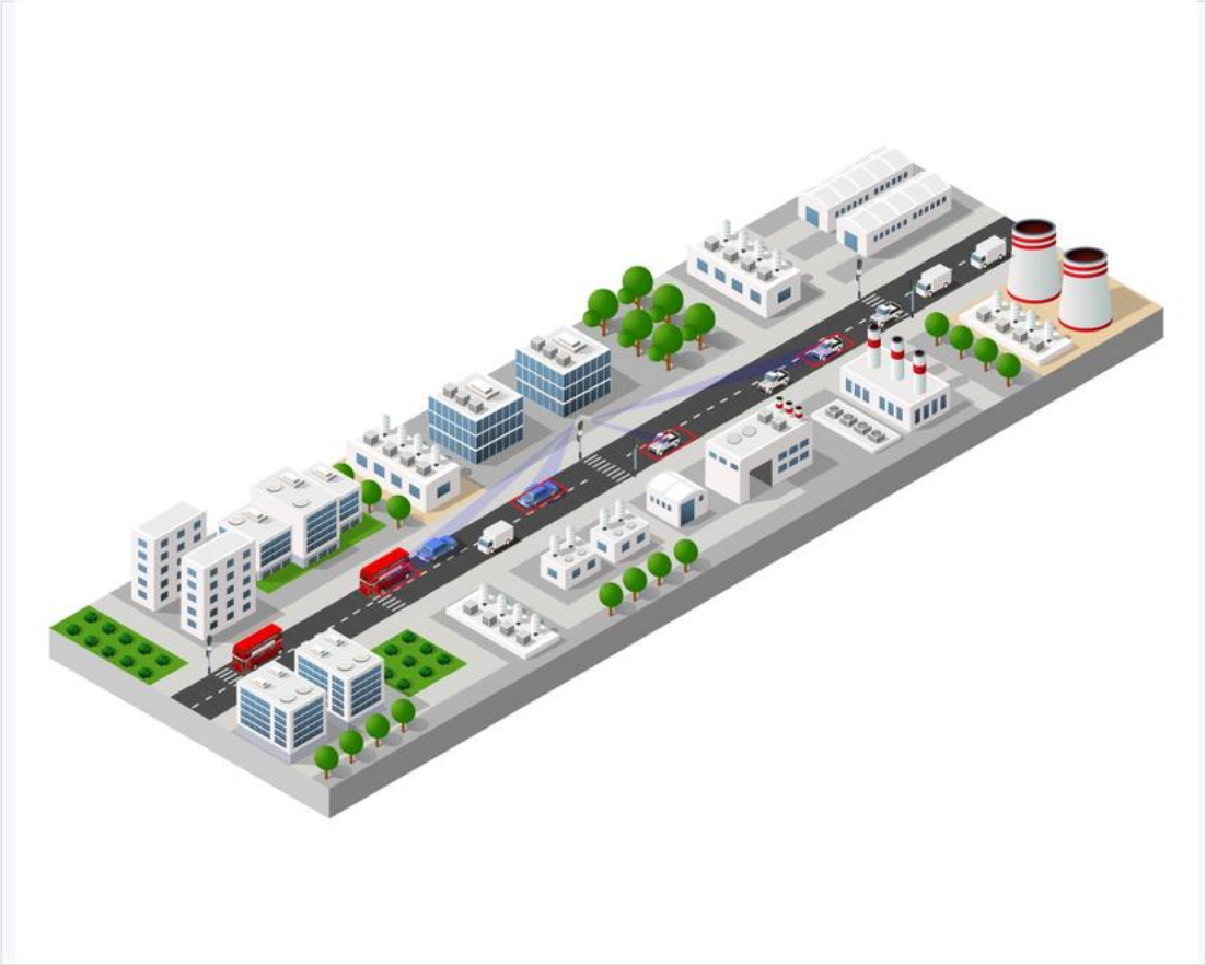
Wireless illuminating the street between junctions — devices added anywhere in line of sight.
How it works
A radio down the street, a chain across the city
A radio is directed down a street. Several compatible devices connect to it before traffic passes to the next node in the chain — signals, CCTV, sensors and signs. Neighbouring nodes provide alternative paths, so eligible traffic reroutes automatically if a node or link fails.
- At the cabinet: a mesh router connects the controller and wired devices to the network and to fibre, Ethernet, ADSL/VDSL or 4G and 5G backhaul
- On the pole: a mesh router takes one powered connection and provides four powered ports for antenna, cameras, sensors and IoT devices
- Between junctions: Intelligent Antennas with headline link rates up to 700 Mbps on 5 GHz, or up to 1 Gbps on 60 GHz in suitable line‑of‑sight conditions
- Backbone links run on our own scheduled channel‑management software rather than in access‑point mode, and do not advertise a conventional network name

A wireless city — one street network chained across the whole area.
The smallest start
Three junctions on one mobile connection
Where a full mesh is not yet justified, a 4G and 5G modem and two mesh links can connect three junctions over a single mobile connection, with an optional camera at the connected site. An appropriately sized AI unit can support the whole cluster — and the cluster can later join a full mesh without being rebuilt.
- One mobile connection serving three junctions instead of three circuits
- Optional camera at the connected site
- AI unit sized to the cluster, not to a single junction
- Grows into the full mesh later; SIM term and data options are agreed per project
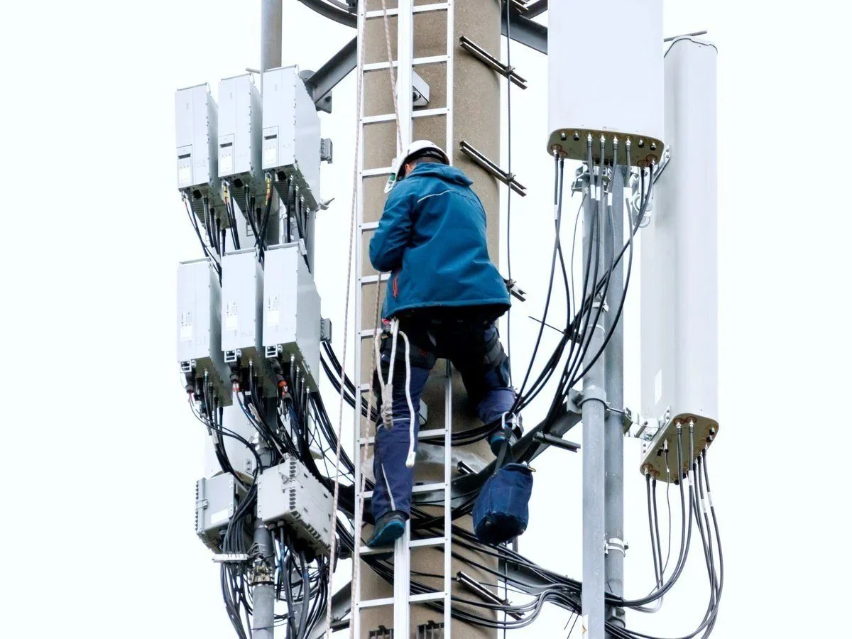
A mobile connection at one site serves the cluster around it.
Part two
See the junction
Once the junction is connected, detection moves out of the road and onto the pole — and the junction starts producing data it never had before.
Detection
Replace loops without cutting the road
Failed inductive loops mean traffic management, excavation, delay and resurfacing. At suitable sites, pole‑mounted AI video analytics provide near- and far‑side detection and present validated outputs to the traffic controller in the same way as approved loop inputs — with detection zones that are drawn, moved and resized remotely.
- Stop‑line presence, approach occupancy and virtual remote loops from one camera
- An additional camera 50 to 100 m upstream extends queue detection
- Zones reconfigured from the desk — no return visit, no road closure
- Vehicles counted and classified into up to 17 types, alongside pedestrians and cyclists
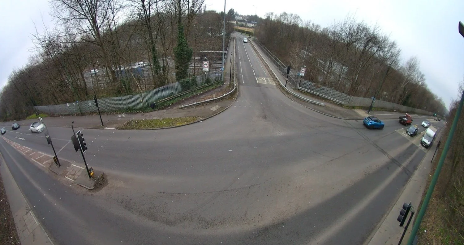
Detection zones on a live junction view from a NOW Wireless camera.
Talking to the controller
Validated detection, presented the way the controller expects
Loop Interface modules present validated detections to a compatible traffic controller as loop signals — eight control lines per module, up to 30 V — or over Ethernet. UTC, UTMC and MOVA (Microprocessor Optimised Vehicle Actuation) interfaces are available.
- Eight control lines per Loop Interface module, up to 30 V, or Ethernet
- Works alongside any controller technology — NOW Wireless does not supply controllers or signal heads
- SCOOT (Split Cycle Offset Optimisation Technique) and MOVA are supported; SCOOT is being superseded by next‑generation adaptive control
- Each safety‑critical deployment is subject to controller compatibility checks, validation and applicable approvals
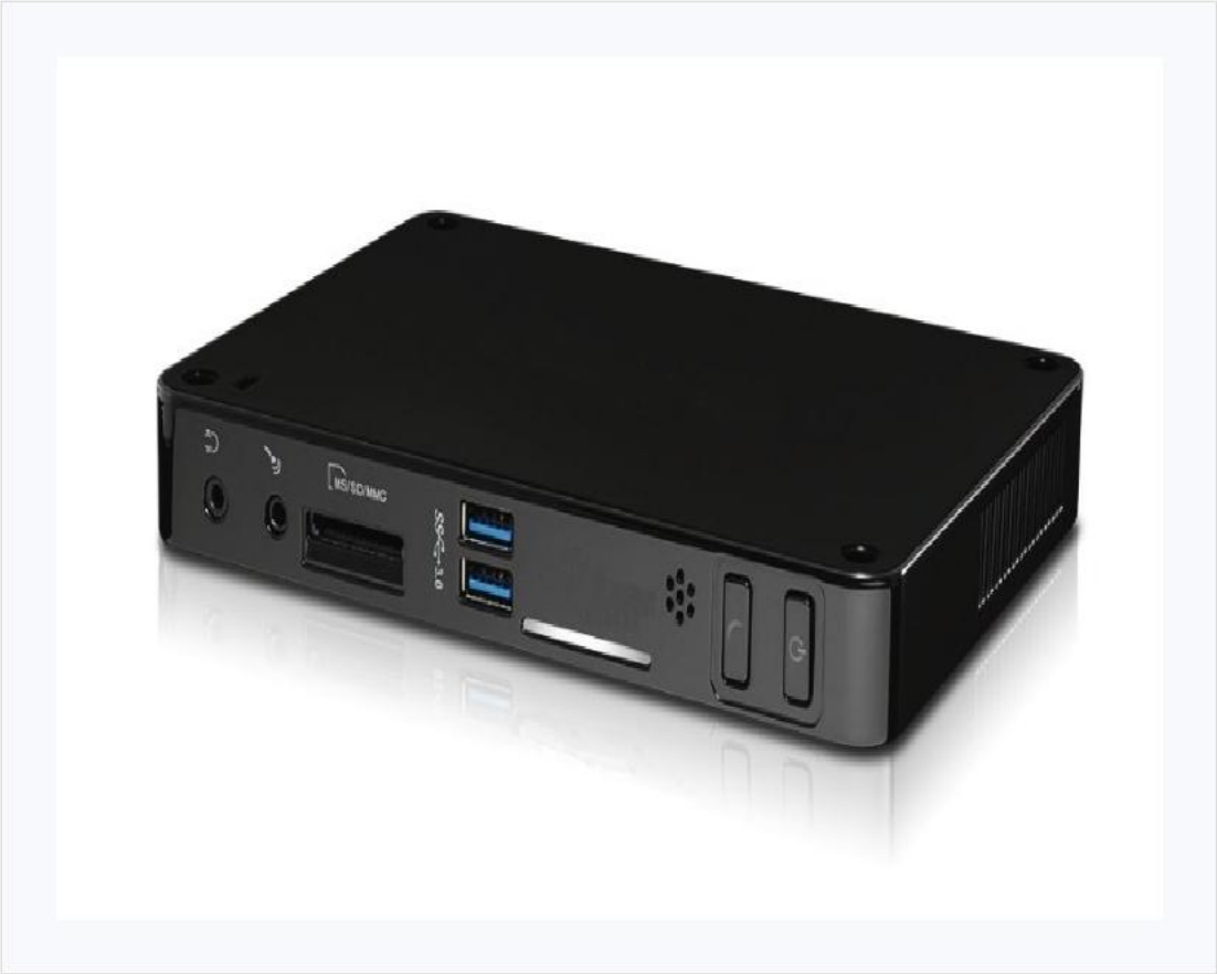
Cabinet‑mounted unit alongside the controller.
Junction hardware
From a single junction to a whole city
A range of AI units covers everything from a single junction to a whole city — matched to the site, not a fixed model. A typical junction uses one unit and four cameras, one per approach, with optional Bluetooth detection. The integrated pole unit combines AI, mesh router and Bluetooth detector in one housing under 5 kg.
- At the roadside: AI on up to 16 cameras per unit — a single junction or a small cluster; pole, cabinet or lamp‑column mount
- In the control room: control‑room AI scaling to hundreds of cameras across the city
- In the cloud: cloud AI tying the whole estate together
- Compatible ONVIF‑conformant cameras can be reused; fixed, zoom and PTZ, very low light and infrared, 2K to 4K
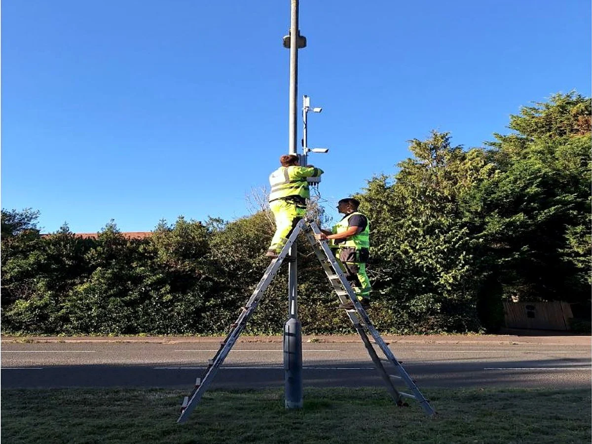
Integrated AI unit going onto a column — a prepared site takes from about 30 minutes.
Feature modules
Activate what you need now, add the rest later
Every junction can be configured with any combination of modules. New modules are added regularly.
Count & classify
Vehicle and mode classification · real‑time turn movements · direct feed to UTC / UTMC · policy‑ready data output
Loop replacement
Replace failed loops remotely · create virtual loops · no excavation works · predictive and advance‑queue loops
Pedestrian detection
Detect real crossing demand · extend green safely · count per area · support active travel policy
Cycle detection
Dedicated cycle zones · separate phase trigger · safer junction flow · continuous cycle counts
Queue detection
Live queue length · adaptive green control · congestion alerts · trigger diversion plans
Journey time
Corridor journey times · origin‑destination data · public information ready · live feed to a UTMC server
ANPR
Vehicle identification · classification and emissions band · Clean Air Zone integration · ghost and clone plate alerts
Camera viewing
Live HD streams · detection overlay view · remote validation · PTZ option available
Part three
Build outwards
One junction becomes a corridor; a corridor becomes a city. The same network then carries everything else the street needs.
Clusters and corridors
From one junction to a smart corridor
Join junction to junction and you have a cluster — a zone where devices share resources. Cameras on one set of signals can stand in for failed loops on another, feeding one AI unit and passing data to the central system. When junctions share data along a corridor, you move beyond isolated intersections into coordinated management.
- Real‑time data sharing within the cluster
- Green waves across connected signals
- Corridor journey times and origin‑destination insight
- Map a mesh cluster onto a signal‑coordination zone so the zone sees classification, camera and air‑quality data, not just loop presence

A corridor of connected junctions sharing one network.
City scale
From three junctions to a city of a thousand
Large wireless networks cover dense urban environments and whole cities. Typical urban hops start at around 100 m, while line‑of‑sight point‑to‑point backhaul can extend to 50 km. Deployed networks connect around 1,000 traffic‑signal locations and thousands of devices; larger designs can support up to 10,000 nodes, subject to traffic profile, topology and capacity engineering.
- Start with a corridor, cluster around each fibre point, then interconnect the clusters
- Each cluster can carry its own 4G and 5G failover gateway on a low‑usage SIM
- Fibre backhaul up to 10 Gbps; multiple converged circuits for greater resilience
- Mesh5G is compatible with earlier Mesh4G equipment, so networks grow without wholesale replacement
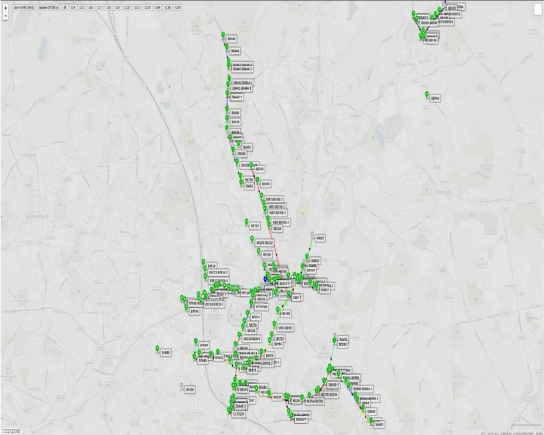
A live county network map.
Mesh manager
Every node, every second, from one screen
The mesh manager — our network manager — creates and operates the street network, polling every node every second, rerouting eligible traffic and self‑correcting when a link fails. SenseView Network sits on top: it watches how well the network is running, remembers each node’s history and flags a node that is failing before the link drops.
- Real‑time map of the network with availability updated every second
- Availability reports — last 3 seconds, last 30 seconds, and weekly split by day and night
- Fault analysis that shows whether the problem is a radio, a node, or a supplier’s backhaul circuit, so the right party is called first
- Remote radio reboot and dynamic frequency allocation resolve many problems without a site visit
- Service‑level evidence per junction, per day, for maintenance contracts and circuit suppliers
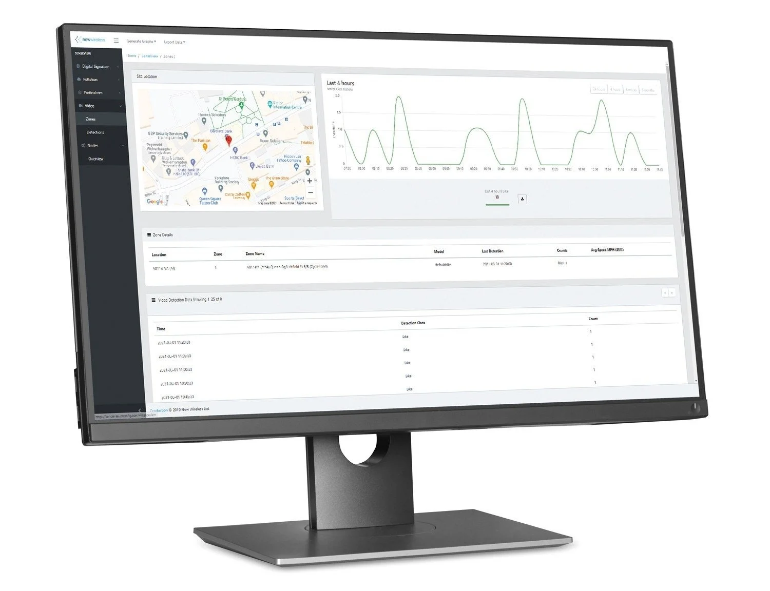
SenseView Network — live availability across the estate.
Everything else on the pole
One street network, not one network per device
Once the node is on the pole, everything else the street needs can share it — without a separate recurring circuit at each location. That is what turns a communications upgrade into a platform.
- CCTV cameras, including PTZ, powered over Ethernet from the mesh node
- XA Series air quality sensors and WS Series weather stations
- Bluetooth journey‑time detectors and ANPR cameras
- Wi‑Fi as an access layer, LoRa (Long Range) for low‑power sensors, and vehicle‑to‑infrastructure gateways where specified
- Variable message signs, bus stop displays and IoT devices
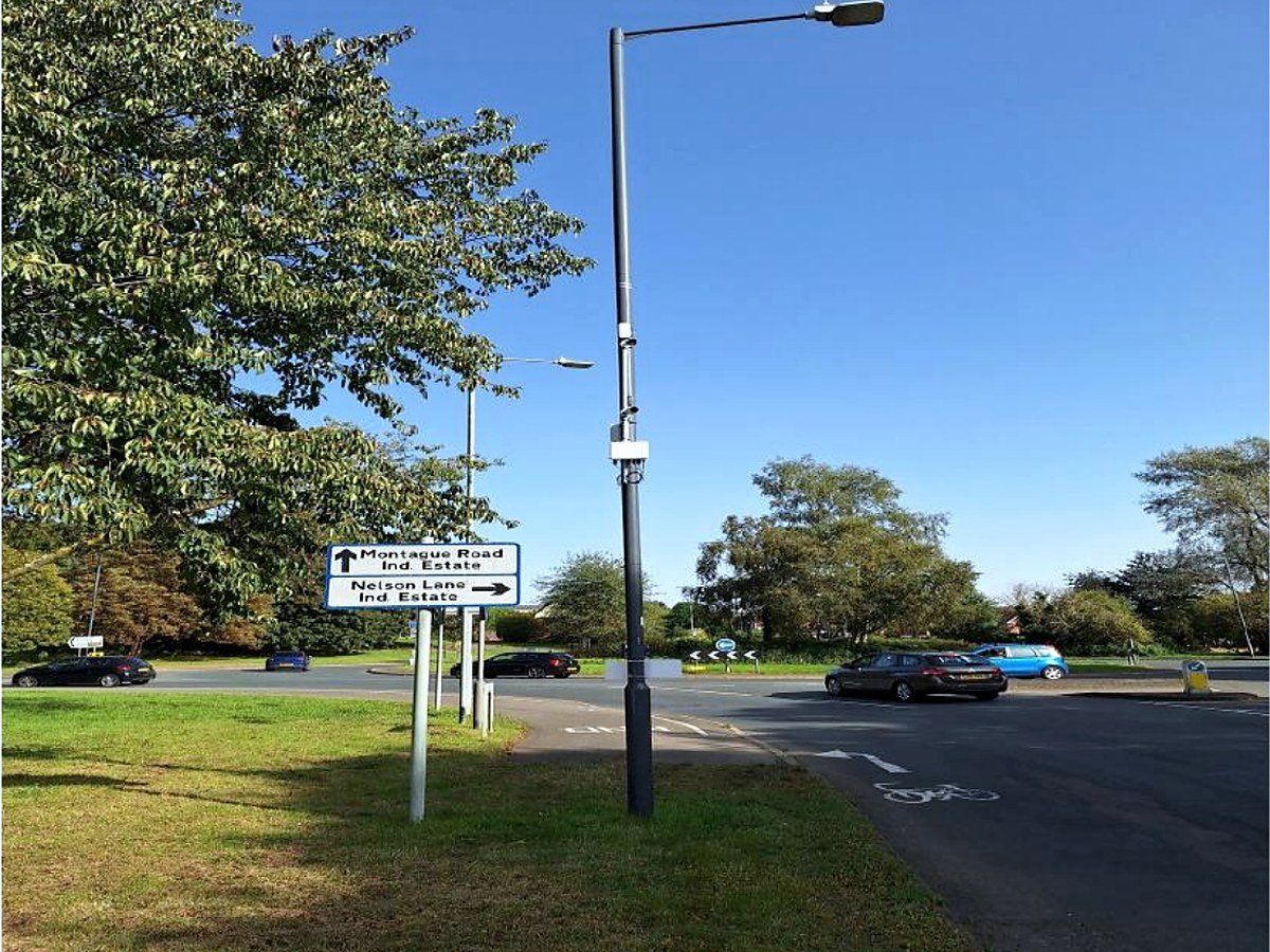
Everything on one column: AI, cameras, mesh, power.
Part four
What the junction knows
Detection, journeys, enforcement and air quality all come off the same node — and land in one platform.
Journeys and enforcement
Know where every journey starts and ends
The same junction node analyses journeys using pseudonymous Bluetooth and Wi‑Fi identifiers, and reads number plates where an authorised use requires positive identification. Outputs include journey times, turn analysis, desire lines and origin–destination patterns.
- BT Series detectors — single, dual and triple‑radio; BT4 combines Bluetooth detection with AI for class‑level journey analytics
- ANPR (Automatic Number Plate Recognition) runs on compatible standard cameras; configured systems are designed for recognition above 95%, and above 98% with suitable short‑range cameras
- Where authorised, approved services return classification and emissions‑band information from national vehicle records for Low Emission Zones (LEZ) and road‑user charging
- Alerts for suspected cloned or ghost plates, and for authorised vehicles of interest
- Bluetooth buttons give authorised buses, ambulances and temporary services a positive identity for approved priority
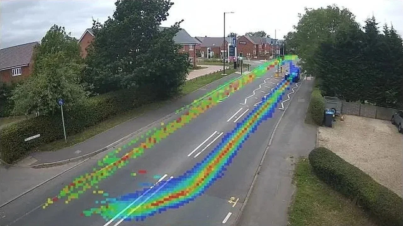
Desire lines drawn on the camera image — how road users actually move through a junction.
Air quality
Predict pollution before it happens
Road traffic is a major contributor to roadside nitrogen dioxide (NO₂), and junction control is a practical intervention point. XA Series sensors connect through the junction node, forecast NO₂ up to an hour ahead, and provide an input to approved UTC strategies — so operators can act before a predicted exceedance rather than report it afterwards.
- Onboard AI builds a continuously updated profile from sensor, traffic, weather and historical data
- In specified trials, forecast accuracy has reached up to 95%; the metric, horizon and validation conditions should be stated for each deployment
- Auto‑calibration compensates for electrochemical sensor drift in software; some units have operated in the field for more than eight years
- Pre‑approved strategies can use green waves, gating or diversions in response to predicted pollution
- WS Series weather stations add mist, standing water and flood warnings on the same node
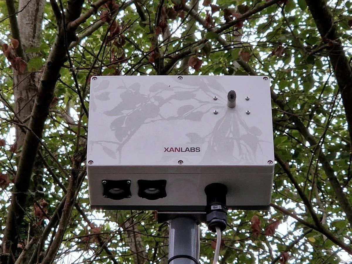
XA Series air‑quality sensor on a street column.
Real‑time data
One data layer, and a working copy of your city
SenseView, our real‑time database, brings junctions, cameras, sensors and mesh nodes into one secure system. It captures data in real time, retains it under configurable policies, executes customer‑approved rules, and connects to compatible UTC, UTMC and on‑street equipment — including third‑party systems.
- Sensor telemetry as often as every 20 seconds; network health polled every second
- Configurable retention, including periods of up to ten years where lawful and operationally necessary, with replay by junction and mode
- Vendor‑neutral: reads existing cameras, counters, signals and sensors through small input/output modules
- Cloud CCTV — role‑based access, PTZ control, AI incident monitoring, video walls of up to 12 streams, retention configurable per customer
- A digital twin of the network is in development — predictive flow modelling and scenario testing are not available as a product today
See the Real-Time Data page for the data layer in full.
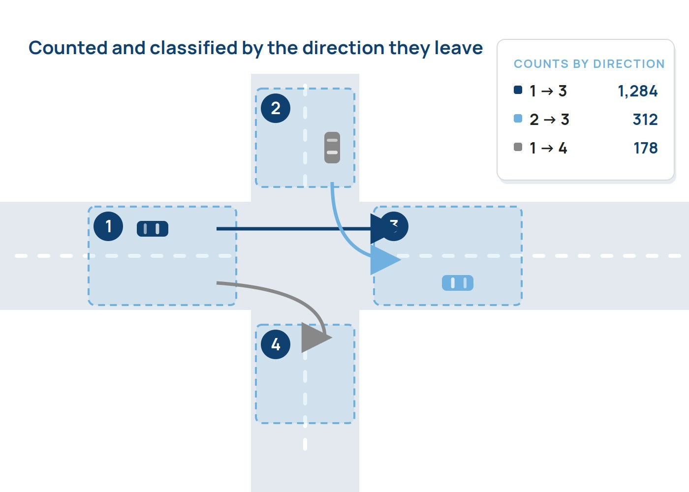
Counted and classified by the direction they leave.
The comparison
What changes when the junction gets its own intelligence
| Capability | Typical loop‑only junction | NOW Wireless junction |
|---|---|---|
| Vehicle detection | Presence and occupancy; classification needs extra equipment | Classified by type and size, up to 17 classes |
| Pedestrian and cycle | Push‑button and separate sensor systems | Real demand detection and counting; dedicated cycle zones |
| Turn counts and queues | Loop arrays or a separate survey | Real time on every arm; live queue length and alerts |
| Journey time and ANPR | Separate systems | Integrated on the same node |
| Air quality | Separate reference station | Forecast up to an hour ahead, feeding UTC |
| Installation | Road works to install or repair | Pole‑mounted at suitable sites; from about 30 minutes per prepared unit |
| Reconfiguration | Fixed detection zones | Zones redrawn remotely from the desk |
| Communications | A rented circuit per cabinet | One self‑healing mesh; up to 90% recurring cost reduction |
Comparisons describe typical installations. Actual outcomes depend on the existing installation, maintenance history, site conditions and programme of works.
Getting started
Four steps, on the cameras and communications you already have
Start with a single junction or a cluster, and add capability as requirements evolve.
Mount
Fit AI cameras to the signal head or pole. Suitable retrofits avoid road cutting; methods governed by site‑specific RAMS.
Detect
Classify vehicles, pedestrians and cyclists in configured approaches; draw virtual loops and queue zones remotely.
Connect
Integrate compatible UTC, UTMC, MOVA and city platforms over the mesh or 4G and 5G.
Optimise
Apply approved adaptive timing, queue management, green waves and pollution‑led plans.
Get in touch
Make every junction count
Talk to our engineers about a trial on your existing junctions — from a single crossing to a city‑wide network.