
Solutions
Smart Junctions
One camera. One junction. Complete intelligence. Put AI cameras on the signal pole and the junction you already own starts detecting, counting and reporting — without cutting the road.
The problem we solve
Your loops are failing. Your junction could be seeing.
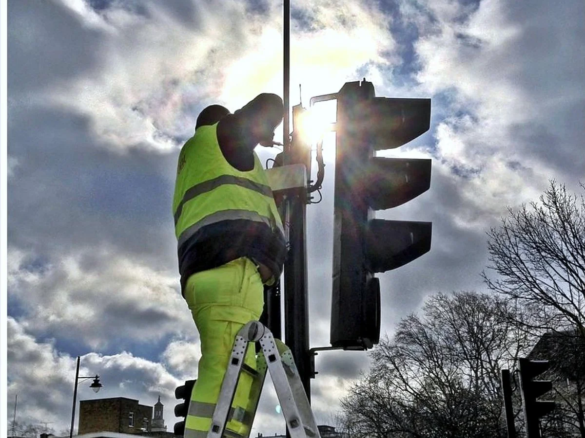
Every signal‑controlled junction depends on detection — and most of it is still inductive loops cut into the road. When a loop fails, the fix is traffic management, excavation and resurfacing for a sensor that only ever said “a vehicle is here”. A Smart Junction moves detection onto the pole: one AI camera per approach, feeding the controller you already have, and producing data the junction never had before.
Figures describe typical deployments. Installation method and outcomes depend on the existing installation, site conditions and the site‑specific risk assessment and method statement (RAMS).
Loop replacement
Replace a failed loop without opening the road
At suitable sites, pole‑mounted AI video analytics provide near‑ and far‑side detection and present validated outputs to the traffic controller in the same way as approved loop inputs. Replace a single failed loop, or draw a detection zone where no loop ever existed — from the desk.
- Replace individual failed loops; create new virtual loops locally or remotely
- Stop‑line presence, approach occupancy and queue zones from one camera
- Predictive loops and advance‑queue loops; an additional camera 50 to 100 m upstream extends queue detection
- Zones drawn, moved and resized remotely — no return visit, no road closure
In‑ground loops and camera detection zones at the same stop line. Zones are redrawn from the desk; a loop is recut in the road.
Detection
Every approach, every mode, every second
One camera per approach sees the whole arm — the stop line, the approach, the crossing and the cycle lane. Vehicles are counted and classified into up to 17 types, alongside pedestrians and cyclists, so the controller responds to real demand rather than a push button or a single presence loop.
- Stop‑line and approach detection on every arm
- Vehicle classification by type and size
- Pedestrian detection — real crossing demand, not just the button
- Dedicated cycle zones with a separate phase trigger
- Live queue length and congestion alerts
Plan view of a four‑arm junction: approach, stop‑line, pedestrian and cycle zones, all from cameras on the signal poles.
Talking to the controller
Validated detection, presented the way the controller expects
Loop Interface modules present validated detections to a compatible traffic controller as loop signals, or over Ethernet. Urban Traffic Control (UTC), Urban Traffic Management and Control (UTMC) and MOVA (Microprocessor Optimised Vehicle Actuation) interfaces are available. NOW Wireless does not supply controllers or signal heads — Smart Junctions work alongside any controller technology.
- Eight control lines per Loop Interface module, up to 30 V, or Ethernet
- Adaptive signal input to existing UTC and MOVA; bus priority triggering
- SCOOT (Split Cycle Offset Optimisation Technique) and MOVA supported; SCOOT is being superseded by next‑generation adaptive control
- Each safety‑critical deployment is subject to controller compatibility checks, validation and applicable approvals
A typical Smart Junction
- Cameras
- 4 — one per approach
- AI unit
- 1, pole or cabinet mounted
- Controller interface
- Loop Interface module or Ethernet
- Optional
- Bluetooth detector, ANPR, air quality
- Communications
- Mesh5G, fibre, or 4G and 5G
- Data layer
- SenseView, UTC / UTMC
Compatible ONVIF‑conformant cameras can be reused; fixed, zoom and PTZ, very low light and infrared, 2K to 4K.
Feature modules
Activate what you need now, add the rest later
Every Smart Junction can be configured with any combination of modules. New modules are added regularly.
Count & classify
Vehicle and mode classification · real‑time turn movements at every arm · direct feed to UTC / UTMC · policy‑ready data output
Loop replacement
Replace failed loops remotely · create virtual loops · no excavation works · predictive and advance‑queue loops
Pedestrian detection
Detect real crossing demand · extend green safely · count per area · support active travel policy
Cycle detection
Dedicated cycle zones · separate phase trigger · safer junction flow · continuous cycle counts
Queue detection
Live queue length · adaptive green control · congestion alerts · trigger diversion plans
Journey time
Corridor journey times · origin‑destination data · public information ready · live feed to a UTMC server
Desire lines
Track vehicle and cycle paths · identify where pedestrians actually cross · detect turning behaviour
Active travel
Real‑time pedestrian counts · cycle counts and tracking · monitor travel hubs · evidence for policy
ANPR
Vehicle identification · classification and emissions band from national vehicle records, where authorised · Clean Air Zone integration · ghost and clone plate alerts
Camera viewing
Live HD streams · detection overlay view · remote validation · PTZ option available
Video & incidents
Streams from all cameras · incident clip storage option · turn analysis streams · ANPR and ghost plate overlays
More coming
New modules are added regularly. Tell us what your junctions need.
How it works
From installation to intelligence in four steps
Start with a single junction or a cluster, and add capability as requirements evolve.
Mount
Fit AI cameras to the signal head or pole. Suitable retrofits avoid road cutting; methods governed by site‑specific RAMS.
Detect
On‑board AI classifies vehicles, pedestrians and cyclists in real time at every approach and stop line.
Connect
Detection feeds the signal controller (UTC, UTMC, MOVA) and the city platform over Mesh5G, fibre, or 4G and 5G.
Optimise
Apply approved adaptive timing, queue management, green waves and evidence‑based policy.
Build outwards
From one junction to a smart corridor
Join junction to junction and you have a cluster — a zone where cameras, AI and data are shared. Join clusters and you have a corridor, then a city.
Clusters and corridors
Junctions that share what they see
In a cluster, cameras on one set of signals can stand in for failed loops on another, feeding one AI unit and passing data to the central system. When junctions share data along a corridor, you move beyond isolated intersections into coordinated management.
- Real‑time data sharing within the cluster
- Green waves across connected signals
- Corridor journey times and origin‑destination insight
- Active travel monitoring across the corridor
- Map a cluster onto a signal‑coordination zone so the zone sees classification, camera and air‑quality data, not just loop presence
Four junctions on one corridor sharing an AI unit and one data layer — green wave, queue detection and journey time from the same cameras.
Connectivity
One street network, not one circuit per cabinet
A Smart Junction connects over whatever the site has: a self‑healing Mesh5G street network, the council’s fibre, or 4G and 5G where a full mesh is not yet justified. Every node carries powered Ethernet ports, so cameras, sensors and signs plug in with no extra circuit — and the network is designed to scale across a city and to carry vehicle‑to‑infrastructure services where specified.
- Mesh5G links change frequency on interference and reroute on failure
- Where a full mesh is not justified, a 4G and 5G modem and two mesh links connect three junctions on one mobile connection
- Fibre clusters: one fibre point serves every street object around it
- In suitable deployments, up to 90% lower recurring communications cost
See Traffic Light Infrastructure for the network in full.
Junctions, CCTV, air quality and Bluetooth detectors on one Mesh5G street network, backhauled by fibre with 4G and 5G failover.
The comparison
Smart Junctions compared with loop‑only detection
| Capability | Typical loop‑only junction | Smart Junction |
|---|---|---|
| Vehicle detection | Presence and occupancy only | Classified by type and size, up to 17 classes |
| Pedestrian detection | Push‑button only | Real demand detection and counting |
| Cycle detection | Unreliable or none | Dedicated zones and phase trigger |
| Turn counts | Loop arrays or a separate survey | Real time, every arm |
| Queue measurement | Not available | Live queue length and alerts |
| ANPR and journey time | Separate systems | Integrated on the same node |
| Video | Separate CCTV system | HD streams, PTZ, incident storage |
| Installation | Road closure and excavation | Pole‑mounted at suitable sites; from about 30 minutes per prepared unit |
| Reconfiguration | Fixed where the loop was cut | Zones redrawn remotely from the desk |
| Active travel data | Manual surveys | Continuous pedestrian and cycle counts |
| Corridor working | Not available | Shared data and green waves across the cluster |
Comparisons describe typical installations. Actual outcomes depend on the existing installation, maintenance history, site conditions and programme of works.
Get in touch
Make every junction count
Whether you are replacing failed loops, improving pedestrian safety or building a city‑wide network, talk to our engineers about a trial on your existing junctions.